This project is now hosted here: http://jjrobots.com/air-hockey-robot-a-3d-printer-hack/
JJROBOTS (http://jjrobots.com) is the new website for this projects: blog, online shop, build instructions, "how it work", forums... more info here
After the last B-ROBOT project, this is what I've been doing the last months...really fun...
Everything started when I built my 3D printer. First, the posibility to design and build my own parts and second, how could I hack the components of a 3D printer to make something different?
I have seen several interesting projects of robots that paint or manufacture PCBs, etc ... but I was looking for something different...
My daughter loves the Air Hockey game and I love robotics so one day an idea born in my mind... can I construct...??... Mmmmm .... it seemed very complicated and with many unresolved questions (puck detection??, robot speed??), but that is also part of the fun...

Based on the idea of use standard RepRap 3D printer parts : NEMA17 stepper motors, drivers, Arduino Mega, RAMPS, belts , bearings, rods, printed pieces ... I started to develop the project. The main advantage of use these parts is that they are cheap and easily available.
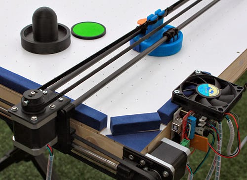
First I started with the construction of the air hockey table. I choose a medium size (my house is small, ;-)) I wanted something easily transportable but comfortable to play. The final dimensions are 100x60cm.
I Bought some wood boards and wood slats and began to mount the table. First I started to build and airless version but it really lacks the feeling so I decided to make a table with air. I tried different possibilities until I test a very simple combination with 2 old PC fans that works very well. I made the table holes (it seemed a hard work but it was not so hard) and I now I had a fully playable Air Hockey table! Time to enjoy it an play!!
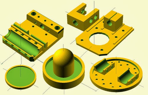
Meanwhile I was designing the robot parts. I think two defferent designs, one H-Bot and another with 3 motors. Finally I decided to use the 3 motor design (2 for the Y axis and one for the X axis). After several design iterations of the pieces, and some material changes to minimize the weight and inertia (and thus increase the accelerations of the robot) I got a fairly operational design. One of the most important change is the replace of the X axis rods with carbon tubes ones (from kites) that works very well on PLA printed bushings and save a lot of weight.
The code: I started studying the code of Marlin ( typical RepRap firmware) software but I decided to start from scratch, first because I don´t need a gcode interpreter and second because the software of a 3D printer have a motion planning algorithm and this is not the way the Air Hockey robot must work. 3D printers plans movements for smooth paths through all the points. The Air Hockey Robot should move inmediately with every new command canceling the previous one, because what we need is that the robot moves as quickly as possible to the new position.
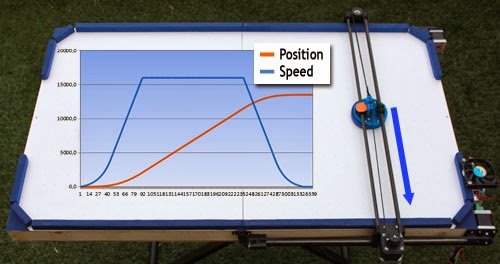
I began developing the driver for Steppers motors using Arduino interruptions and making the code as efficient as possible. I implemented position, velocity and acceleration control, using an acceleration ramp with a simplified S-profile.
The interrupts can generate pulses up to 25Khz which is the maximum speed that I can achieve with the steppers. The position control works at 1 kHz.
For the puck detection problem I decided to use a computer vision system.
Initially I planned to use the CMUCAM5 (Pixy) sensor that fits very well in this project (and in near future I will prepare a version for this sensor), but the camera is not available yet, so I started a new route: Use the PS3 EYE camera with a PC to develop the vision system. I developed the vision system in C lenguaje using OpenCV libraries for capturing, thresholding, filtering and segmentation.
The system detects the puck (must have a special color) and the result is sent to the Arduino by serial port. The vision system sends information packets containing the position of the puck and the robot in pixels within the image. The camera is running at 60Hz at a resolution of 320x240. Fortunately the camera has very little distortion and I don´t need to implement a lens distortion correction. The software records a video on the PC which is very useful for debugging.

One of the main problems I've had is that the power of the NEMA17 motors are pretty fair for this project and the disadvantage of using stepper motors is that if we lose steps (which can easily happen, for example when the robot hits the puck against the wall) and we do not take into account the missing steps we lose the position of the robot. To fix this, what I've done is to use the vision system to detect also the robot (with a different color) so we can detect when the robot has lost steps and fix it.
What remained was the implementation (in the Arduino) of the trajectory prediction system and the strategy of the robot. Once we have detected the puck in two consecutive frames we can calculate the trajectory (equation of the line through two points, this is college math!). The trajectory prediction takes into acount that the puck could bounce in a side wall. All these calculations are accesible to the strategy subsystem that decides what the robot will do: defense, defense+attack of prepare a new attack.

A nice part of this project is that the Strategy subsystem is fully insulated and is very easy for everyone to modify this part and program their own strategy algorithms isolated from the complexities of motor control, vision system and prediction code. The strategy is what makes the robot wins or lose! so in the future we could see Air Hockey robot competitions?
Although it can seems a complex project, it´s an affordable and doable project.
- Code repository, 3D designs, documentation link: GitHub
- Detailed build Instructions link: Build manual
Some other considerations that have been taken during into account in this projectt (and the future):
- The project is reproducible: Easy to get materials, documentation, open source code and open hardware ...
- The robot is removed completely from table with only 6 screws. So it can be removed for play or transport
- It's very easy to adjust the level of the robot, for example to play with children, just turn down the acceleration and maximum speed of the robot (this could be improved in the future)
- Currently the robot is not able to detect goals but we could improve this in future.
- In future the robot can self-calibrating the camera using predefined movement at beginning (to avoid the camera calibration).
- We could mount two robots per table, one on each side. Competitions between robots?? Compare different strategies in a tournament? ...
- It's a great and fun project to teach science specially for childrens:
- Concepts of Physics: Friction, continuous and uniform motion, rebounds, concepts of position, speed and acceleration
- Mathematical Concepts: Equation of the line through two points, prediction, XY Cartesian System
- Robotics: Motors, Machine Vision, Control, Arduino
- DIY Philosophy: Build your own Air Hockey table
- Hacking: Using 3D printer parts to build something completely different.
What is the current robot skill? Well, now the robot could easily beat a child. An adult with some experience (myself, lol) can still win the robot, but I am sure that with some more small improvements it is going to be really hard to beat ...
The project is fully alive with undergoing improvements, both in code and the robot ... all contribution to the project are welcome ...

Remember, future improvementes will be hosted on JJROBOTS (http://jjrobots.com)
Science & fun
Jose Julio (@ jjdrones) JJROBOTS.COM (@jjrobots)
Great project!
ResponderEliminarAwesome! Great job!
ResponderEliminarThis is really the best project I have seen in a long while!
ResponderEliminarEste comentario ha sido eliminado por el autor.
ResponderEliminarYou are doing really great things! Thank you so much! :)
ResponderEliminarI also like your past projects http://www.diydrones.com/profiles/blog/list?user=3n7oxlg4fanvy
Now B-robot and Air Hockey. Quality design and documentation! Very very cool!
Make sense to move it on Kickstarter! ;)
p.s. Where you take time for all of your projects? :)
You specified that camera is running at 60Hz at a resolution of 320x240.
ResponderEliminarBut PlayStation Eye 3 can give you 120hz at 320×240 (or 60hz with 640×480 resolution). Where more speed will give more precise with capturing point coordinates.
Thanks!
EliminarI use 320x240 resolution at 60hz because my laptop is not able to process the 640x480 resolution...
Hi , great job. What is the price for this device ?
ResponderEliminarThe price is a bit less than a typical reprap 3D printer (for example a prusa) because it has less motors/drivers and no need hotend and the cost of the wood for the table is cheap. I have no an exact calc but should be around 200€ (without the PS3 camera and laptop).
EliminarFound your project via a Dutch News Site:
ResponderEliminarhttp://www.nu.nl/tech/3696347/3d-printer-omgebouwd-slimme-airhockeyrobot.html
Cool project! Very nice how you describe it with enough but not too much detail.
Muy bien (Y)
ResponderEliminarAwesome!
ResponderEliminarAmazing !
ResponderEliminarGreat Job!
ResponderEliminarYou are awesome~!!Caring father
ResponderEliminarVery nicely done. Thanks for the post.
ResponderEliminarPero ¿qué significa cacharreo?
I don´t know the exact translate of "cacharreo" but could be something like tinkering, experimenting, play with electronics....
EliminarImpressive to see how fast your system responds. Opens my mind to possibilities. Thanks for sharing this.
ResponderEliminarAwesome! Simply superb work!
ResponderEliminarI _REALLY_ want to see what happens when you build a second robot, and have them play against each other ...
ResponderEliminarAwesome work, Jose!
ResponderEliminarI totally want to build one, too. Can you recommend any resources (such as books, online-resources) about the know-how required for this project (Arduino, etc.)?
Wow! Well Done - the robot has impressing reaction time and skill! Very good job and world class idea! I´ve written a small article on it in my blog to (in german) http://www.ddd-druck.at/3d-drucker-umbau-in-air-hockey-robot/
ResponderEliminarAmazing! Great job!
ResponderEliminarHow do I increase the size of 160cm x 90cm table?
Thank you.
Yes, you could build it bigger but maybe you would need to change the motors to something bigger like NEMA23´s...
EliminarHi Jose!
EliminarIf I increase/decrease the size of the table. Do I need to change any dimensions or parameters in the coding?
Thanks.
Fantastic job Jose !!!
ResponderEliminarDo you think it could be possible to do the same but down sizing ?
Nema14, CoreXY system (only 2 motors for all) and especially in A3 format (so portable) ?
Many thanks for your creativity and sharing.
Gilles
http://www.corexy.com/corexyr1/index.html
EliminarCoreXY system maybe increase speed and reactivity because of no motor to move...
Thanks for your suggest, yes we could build a smaller version (I think that is always easier to shrink than grow). An small and portable version could be very attractive...
EliminarI was thinking in something like a CoreXY (an H-BOT configuration) but the problem of this configurations is that it needs a robust base or you have problems with belt tensions and also it has the problem that a diagonal move has less torque (beacause it uses only one motor) but it would be a good test.
Can it handle curved trajectories?
ResponderEliminarBeacuse of the frictionless enviroment (because of air) the trajectories are really straight, one problem is that the puch could have effect and this change the bounce trajectory and could fool the robot until it "reads" the new trajectory...
Eliminarthank you to you Jose for this answer so rapid.
ResponderEliminarCould keep NEMA17 (not so big in fact) and all pulleys on bearings and using fishing line sea, which resists at big tension.
The heart of your project is really the part of optical processing that you wrote, which interface with the arduino! ... For a portable version, do you think it would be possible (CoreXY) to use only 2 Polulu stepper + Arduino UNO for example, or the work frequency is too high?
@ +
Oh ! and only one carbon tube would be necessary for the X axis ?
EliminarWhat do you think ?
Gilles.
CoreXY could be a good option (specially for a little version) with the advantage of use only 2 motors. The code is small enough for an Arduino UNO but maybe you could have problems with RAM memory (not enough on the UNO).
EliminarI had a look at the Pixy sensor. Will the robot get even better with those 50 fps the camera offers or is it just a more elegant solution? It would also be interesting to know if the positioning algorithm would also work if the camera is positioned above the robots goal (and not centered above the table), with triangulation?
ResponderEliminarThanks anyway for posting this, you totally got me hooked on microcontroller stuff. ;)
I was thinking on the Pixy sensor (CMUCAM5) because this way we don´t need an external laptop, so i will be an arduino only (plus camera) project. Actually the vision system runs at 60Hz 320x240 resolution, with Pixy it will run at 50Hz but 640x480 resolution. I think it would perform in a similar way... I will compare ;-)
EliminarIf you put the camera above the robot goal you will need to make a perspective correction but it´s posible (this was the first option I thinked). With the actual position the calculations are easier.
REALLY impressive,
ResponderEliminarnice work, and nice smile at the end, you did it :)
Hello Jose, why didn't you chose the RASPBERRY-PI + RPI CAMERA BOARD a such very cheap package for a standalone system ?
ResponderEliminarI have seen some projects running OpenCV on Raspberry PI and I think they could not reach the 50-60fps processed needed for a real time robot like this...
EliminarI'd like to see two of these playing against each other!
ResponderEliminarFantastic! What a great project. Have you thought about taking this to production?
ResponderEliminarI have no plans for production now but it seems to be many people interested in projects like this. Now I am working to improve the project...
EliminarBrilliant work!
ResponderEliminarThe forever alone dream!!! :-)
ResponderEliminarThis is a very powerful design
ResponderEliminarI really want a Air Hockey Robot
Great Job Jose Julio!
ResponderEliminarYour explanation makes it seems easy, but it's not!
Are you thinking about a 3D ping-pong game with two cameras and one quadcopter? It would be a challenge!!
Este comentario ha sido eliminado por el autor.
ResponderEliminarHey. Could you clarify exactly what specifications with NEMA17 motors are used on the project. On ebay a huge amount of different versions of this engine.
ResponderEliminarI used NEMA17 motors like this: 42BYGHW811. Motors with 4.8kg/cm of torque. This are the same that most people use for reprap 3D printers....
EliminarWonderful project and implementation. Well done!
ResponderEliminarexcuse me, how do you choose the stepper motor?
ResponderEliminarEste comentario ha sido eliminado por el autor.
EliminarHi, Nice project congratulations. Can we develop this project and made a product for a commercial? Nice toy. May have a big market poriton in toy machines sector.You should think for a commercial.
ResponderEliminarWhat specification is the OpenCV computer? CPU name, core number, clock frequency, RAM, etc. USB2 (not USB3) is used, right?
ResponderEliminarI modified an inexpensive air hockey table for this project and made floating x carriage and pusher.
ResponderEliminarThe files are at http://www.thingiverse.com/thing:266316. This seems to work quite well Julio. Completely 3D printed,only two parts,no screws and less weight on the X carriage. I'm able to use a thinner ,lighter puck and the pusher height issue is solved even if the MDF board warps slightly.
Thoughts?
Hi Robert, thanks for share!, it seems a good idea, specially if you have problems with the flatness of the surface... Beacuse the two parts are not screwed together do you think that you could lose some power on the hit? In your video it seems to work pretty well... Congratulations...
ResponderEliminarPower doesn't seem to be a problem. Inertia keeps the carriage flush with the pusher at point of impact regardless of trajectory. I am not getting 1/8 stepping though. I am going to replace the step sticks (they are old) and see if i can travel 5cm on the motor test. Currently I'm only getting 2.5cm . I am using the proper tooth count on the belts and the gears came out great. Looking forward to any updates you might have. I value your opinion.
ResponderEliminarRespectfully Robert
Great!. If you are getting only 2,5cm move it seems (as you say) that you are using 1/16 microstepping (this is the default). You need to remove one of the jumpers on the RAMPS (it´s documented on the build manual) in order to configure the 1/8 Microstepping. I am testing the new DRV8825 drivers (they are more powerfull) and it seems to work well, but I need to modify the code to make it compatible with this drivers. I will probably update the code this week (with some improvements in strategy also).
EliminarKeep us informed with your progress...
Robert, if you need to contact me (by email) you could use the contact form on the right side of the blog (Name, email and message).
Jose.
Flipante!!
ResponderEliminar(lo encontré vía http://3dprintingindustry.com/2014/03/12/3d-printing-air-hockey-robot/?utm_source=Facebook&utm_medium=social&utm_campaign=3DPI%2BFacebook)
excuse me, how to tracking the ball?
ResponderEliminarI dont't how to define the function
Hi
ResponderEliminarI start biuld AirHockey ... I have working PS3 camera ( with test program from CL-EYE Test) but when i start program CHECK_HSV - program start-... show some frame and close - exactly same like without Camera ( Win7 64bit I3 DELL Vostro 4GB RAM ) --- Have You any ide why ??
Hi, i have problem exactly on your problem in ps3 cam can you help me?how did you solve your problem
Eliminar... I use driver from this link.. http://codelaboratories.com/get/cl-eye-driver/
ResponderEliminarCL-Eye-Driver-5.3.0.0341.exe
:-) problem solved.... after switch of build in CAMERA in my laptop - program start correctly with external CAM PS3 :-)
ResponderEliminarI am happy you could resolve your problem. I have tested on two different laptops and works fine.
EliminarAs I wrote - probelm was internal camera start with Your APK as default...
EliminarI'm wondering... If two robots are playing against each other - will it be the "perfect" game? If the mechanics, electronics and the software is the same will they be able to score a goal? :)
ResponderEliminarGreat project, Jose! I love the air hockey game, too! I think that I will try to make this robot after finishing my Prusa i3 that I'm building right now... :) Thank you!
Thank you for posting the updates Julio. I will be able to try them out early next week.
ResponderEliminarRespectfully,
Bob
Hello, we are a group of four french students working on a project at school. Basically, it is a camera tracking a moving object. You seems to know a lot about open CV and we would like to know if we could talk using E-mail. You can contact us at projetlava@gmail.com
ResponderEliminarThank you very much
Lucille, Alice, Vincent and Adam
What a great project!
ResponderEliminarI have a question:
Did you put a gearbox between the stepper motors and the belts? Or are they connected straight forward?
The steppers are connected directly to the pulley and belts...
EliminarFantastic work, congratulations!
ResponderEliminarGiven that I want to accomplish your project, you wonder if you have made substantial changes to the software / ardware.
Thank you,
regards,
Gerry.
Updates worked well Julio. Thanks again.
ResponderEliminarHi Julio,
ResponderEliminarThank you for making your project public and providing such detailed instructions! A couple of us at the University of Maryland are replicating your project. For future reference, however, we'd recommend that in the instructions you list 5 meters of GT2 timing belt, not 3 meters. We found that 3 meters was a bit too short. Also, it'd be helpful to mention how you connected the timing belt together - we ended up stapling the ends together.
Thanks again!
Thanks! updated to 5 meters on the build manual...
Eliminar:-) job in progress >>>. https://www.youtube.com/watch?v=sY7W6-kVB1c - this really works ... ;-)
ResponderEliminarThanks for share!!! Nice work! keep me informed of your progress please...
EliminarEste comentario ha sido eliminado por el autor.
EliminarSome test VISION system https://www.youtube.com/watch?v=Dlu3sy-MVnI
EliminarVery nice SP good video.
ResponderEliminarThis is an awesome project!
ResponderEliminarI'm going to be setting it up on a big table with a black (instead of white) table. Will this effect the tracking of the puck? If so, how can I tell the camera which colors to ignore, and which colors to focus on for the puck and the pusher? (I am printing it out on green ABS)
I think that there would be no problem on use a black surface. The vision system looks for the color of the puck and the robot mark. You define the colors on the vision system call (is documented on the doc)
EliminarEste comentario ha sido eliminado por el autor.
EliminarDo you think NEMA 14 motors would be powerful enough if I adapted the printed parts to fit? I have an unfinished RepRap Huxley that I could salvage parts from.
ResponderEliminarNEMA 14 have not enough power for this project, you will need to build something much more smaller for these motors...
EliminarThanks, I figured they might be, I've already built the table so I'll buy some NEMA 17s for it. My Hackspace has a A0 laser cutter which I've been making use of for this project, I'll post all of my design files soon but you can see some photos of my progress: https://plus.google.com/photos/115399656207465585576/albums/6027665582157139521?authkey=CLeq5Jvzs96tiQE
EliminarWow! Excelent work! I want one of this laser cutters for christmas ;-)
EliminarThank you for sharing it!
ResponderEliminarI will be doing this on a VERY big table: (90inch x 50 inch). Will the NEMA 17 be strong enough for this size? Should I use something stronger? Will the rods start flexing/bending at these lengths?
ResponderEliminarThat is too big for this motors in my opinion! This motors are a bit weak for this project, you will need something more powerfull... Also you need bigger rods...
EliminarI am getting a lot of compiling errors when I try to upload the software to the Arduino. Here are the errors I am getting:
ResponderEliminar(This is from the Motor test program)
AHR_Motor_Test.ino: In function 'void setup()':
AHR_Motor_Test:47: error: 'Z' was not declared in this scope
AHR_Motor_Test:47: error: 'ENABLE' was not declared in this scope
AHR_Motor_Test:47: error: expected `;' before ':' token
AHR_Motor_Test:59: error: 'A8' was not declared in this scope
AHR_Motor_Test:119: error: 'TCCR3B' was not declared in this scope
AHR_Motor_Test:121: error: 'TCCR3A' was not declared in this scope
AHR_Motor_Test:132: error: 'OCR3A' was not declared in this scope
AHR_Motor_Test:134: error: 'TCNT3' was not declared in this scope
AHR_Motor_Test:145: error: 'TIMSK3' was not declared in this scope
Steppers.ino: In function 'void __vector_11()':
Steppers:32: error: 'PORTF' was not declared in this scope
Steppers.ino: In function 'void TIMER3_COMPA_vect()':
Steppers:58: error: 'PORTF' was not declared in this scope
Steppers:59: error: 'PORTL' was not declared in this scope
Steppers.ino: In function 'void positionControl()':
Steppers:92: error: 'PORTF' was not declared in this scope
Steppers.ino: In function 'void setMotorXSpeed(int16_t, int16_t)':
Steppers:174: error: 'PORTF' was not declared in this scope
Steppers:183: error: 'PORTF' was not declared in this scope
Steppers.ino: In function 'void setMotorYSpeed(int16_t, int16_t)':
Steppers:236: error: 'PORTF' was not declared in this scope
Steppers:242: error: 'PORTL' was not declared in this scope
Steppers:252: error: 'PORTF' was not declared in this scope
Steppers:258: error: 'PORTL' was not declared in this scope
Steppers:274: error: 'OCR3A' was not declared in this scope
Steppers:276: error: 'TCNT3' was not declared in this scope
Make sure you have selected the correct board from the "Tools" menu, it should be the Arduino Mega.
EliminarThanks for the help Rob, I agree, it seems that you selected another board...
EliminarHi, Mr. Jose Julio i would like to ask what language did you used in your air hockey robot...and what software did you used in the camera to locate the puck
ResponderEliminarI use Arduino for the robot and C for the camera software. Check the documentation links above, you have all the info...
EliminarWhat vision software did you used for ps3 eye cam and to detect the puck and robot
ResponderEliminarhi jose im having a problem with the ps3 camera, i follwed the initial steps ...until i need to open the "AHR bat" file... two windows open....one in a command prompt window with values COM19 AHR.exe 70 94 60 150 10 146 5 20 110 200 90 200 60 and the other window just displays a black window with some numbers on the top left and right side...im not sure what has gone wrong here but i dont seem to get any proper image..can someone help me??? pls thanks
ResponderEliminarCheck that you have installed properly the driver for the ps3 camera (the driver has a test program)
Eliminari having problem with ps3 cam too and i followed your instruction and I installed properly the driver for ps3 cam and i run the test test program for ps3 cam and its work but when in going to run the CHECK_HSV and AHR.bat windows for video is till black what should i do?
Eliminar1.Check your com port in arduino . Right click on the Bat file and select edit to change COM19 to the correct com port. The screen will remain black until you start adjusting the sliders. After you have made the puck white with all black background click save and edit the corresponding numbers in the Bat file. Repeat the process for the pusher and click save once again. In both cases you want an all black background and a white pusher / puck. I hope this helps.
ResponderEliminarHI
Eliminarcan you help me in my problem it cant detect my puck and bots and I also follow your instruction but it stille cant detect the puck and robot
Hello
ResponderEliminarWith some friend, we have made One ! and it's works well !
Now I try to suppress the computer and I use a RASPBERRY.
I modifie your program to be compiled on Raspi
When I use the same HSV parameters, the camera don't find the puk and the bots.
So could you give the source of your CHECK_HSV program. I want to compile it under linux for calibrate the software.
For the moment the Raspi seems to work (CPU less than 60%).
I use only terminal. I don't show camera view to increase performance.
Thanks
Great!! Welcome to the air hockey robot league ;-)
ResponderEliminarUsing a Raspberry seems a good idea (if finally has enough power). I uploaded the CHECK_HSV.cpp source code (I think this is the last version I used) to the GitHub repository (under VisionSystem/PS3Camera) Good luck and keep us informed please...
Thank you for sharing this information
ResponderEliminarRaptor Software Visitor Badges
Thanks for CHECK_HSV.cpp.
ResponderEliminarThe result is different between raspi and Windows !!
I have some problem to detect the bots. I will change the color
For the puk no problem!
HI,
Eliminarhow did you solve your problem in bots? can you help me? i have same problem on you.
it cant detect my robot to
HI JOSE
ResponderEliminarI HAVE PROBLEM IN "CHECK_HSV apps files" went im going to run it will open and in a few second it will close automatically what should i do?can anyone here help me in my problem
I remember I had to disable my Laptop Cam in device manager in order for "CHECK_HSV to work properly with my PS3 cam. This effectively makes the PS3 your default cam. I expect others may have had to do this also.
Eliminari solve the problem for the ps3 cam but theirs a another problem it cant detect the robot and i already check the CHECK_HSV its still cant detect the robot
Eliminarwhat should i do please help me
i solve the problem for the ps3 cam but theirs a another problem it cant detect the robot and i already check the CHECK_HSV its still cant detect the robot
ResponderEliminarwhat should i do please help me
If the CHECK_HSV app is working ok, you should find the values to detect the puck and the robot and rewrite this values on the AHR.BAT to launch the vision system,
Eliminari do what did you say but still cant properly detect the robot and cant move properly can i get your email that can i send the video output in our AHR
EliminarYou could send me an email using the contact form on the right side of the blog
EliminarEste comentario ha sido eliminado por el autor.
ResponderEliminarcan i get the schematics or circuit diagram of the project,also can we use smps 300w to power the system,then how will the connections be?
Eliminarour table size is 180 cm x 120 cm, is nema 17 adequate for this size?
If we are implementing the project for x axis ie horizontal only then what changes will occur to the program
please reply as soon as possible
Hi, there are a lot of documentation on the build manual. For your table size, NEMA 17 are underpowered, you will need something more more powerfull... You will need to change the code to operate only on X axis...
Eliminar